An AltaRica node is a component of the system. Its interface with its environment is divided in two parts: events and flow variables. The first ones represent actions of the environment or of the component itself, in fact any phenomenon that can change the state of the component. Second ones are shared variables that can be used to model data circulating into the system.
Events may change the state of the component; this one is described by the mean of state variables. While flow variables may evolve according to modifications of the environment, state variables change only on occurrence of events; this means that between two events of a node the value of its state variables do not change. In the sequel, an assignment of state and flow variables is called a configuration.
The changes of state variables on event occurrence is described using transitions. The relationship between flow and state variables is described by means of assertions.
The description of a node starts with the keyword node and terminates with edon. The name of the node is given after the node keyword. Since a node may occur several times in a system (e.g. a switch), each node description defines a type of nodes. Actual instantiation of nodes is done in the sub section of hierarchical nodes.
1 node Component
2   ...
3   ...
4 edon
Variables
Declarations of variables are introduced by the keywords state or flow according to the kind of declared variables. Declarations consist in a comma-separated list of identifiers followed by a colon (:) and the domain of the variables. Each declaration is terminated by a semi-colon (optional for the last one).
1 node A
2   flow input : bool
3   state memory, status : bool;
4   flow output : bool
5 edon
Generic attributes can be attached to variables. Theses attributes are simply labels that are interpreted by tools; they are given after the domain (a colon separates the domain and the list of attributes). The following example associates orientation attributes, in and out to flow variables. Remember that in and out are just labels and have no particular meaning here; the semantics of these labels is specific to each tool (e.g. the translator to the Lustre language).
1 node A
2   flow
3    a : bool : in;
4    b : bool : out;
5    ..
6 edon
The init keyword introduces the initialization part of the node. Only state variables can be initialized. Remember that flow variables are shared variables thus their initial valuation can not be specified by a simple assignment. As explained below the value of flow variables depends on state variables and the environment of the node; this is also the case for their initial values. init is followed by a comma-separated list of assignments (:=) of state variables. The semantics of AltaRica nodes considers that not initialized variables may take any possible value in their domain (up to assertions satisfaction) at the initial state.
1 node Gate
2   flow in, out : bool
3   state closed : bool;
4   init closed := true;
5 edon
Events
Events are labels used to represent state changes. The declaration of events is introduced by the keyword event followed by a comma-separated list of identifiers. Like variables attributes can be attached to event. The following example presents a switch node with three events: open, close and stuck. Two attributes can be used to indicate that open and close are normal actions and that stuck models a failure.
1 node Switch
2   event
3     open, close : action;
4     stuck : failure
5 edon
Each node is equipped with an implicit event called ε (epsilon). This event denotes the idleness of the node and is always possible/enabled (see transitions).
Assertions
Assertions are Boolean expressions used to describe invariants on variables. All configurations of a node must satisfy specified assertions. They are introduced by the keyword assert. Assertions are listed using a semi-colon as separator.
These invariants can be used to describe relations between flow variables as a transfer-function but also they model relationship between states of the node and the value of its flows. The following example describes a node that simply translates some Boolean “input” into an integer “output“.
The translation of the Boolean “input” is written using an assertion that specifies that when input is true then output is 1 and 0 in the other case.
1 node Translate
2   flow
3    input : bool;
4    output : [0,1];
5   assert
6    output = (if input then 1 else 0);
7 edon
In the previous example, the syntax used to describe the value of output according to the one of input is quiet intuitive but it can make readers think that output is assigned the value of the If-Then-Else expression. This is not the case; assertions are just Boolean expression thus the previous assertion can be rewritten by inverting operands of the equality:
(if input then 1 else 0) = output;
or by incorporating output variable into the If-Then-Else:
(if input then output=1 else output=0);
and even by splitting the constraint in two implications:
input => (output=1);
not input => (output=0);
Transitions
Transitions describe state changes. Each transition is composed by:
- a Boolean expression called a guard that represents a necessary condition to make the transition enabled;
- the name of the event that induces the state change;
- a list of assignments of state variables.
Transitions are introduced by the keyword trans.
On the occurrence of an event e in configuration c, a transition t labelled by e is said to be enabled if its guard is satisfied by c and if all assertions are satisfiable after the assignment of state variables. In a given configuration if a transition t is enabled then it can be triggered and the node enters some new configuration computed as follows:
- State variables are modified according to the transition t and not assigned state variables keep their current value;
- Assignments of flow variables are those ones that satisfies assertions.
This semantics implies that values of flow variables only depend on state variables and not events. In the sequel remember that:
- state variables are modified by transitions according to the current configuration;
- flow variables are computed according to state variables and assertions.
Below we give an example of a node that models a counter. The value of the counter is memorized into a state variable counter_ and is shared with the environment using a flow variable value. The environment can modify the value of the counter using three events, inc, dec and reset that respectively increment, decrement and reset the counter.
 1 const CMAX = 5;
 2 domain COUNTER = [0, CMAX];
 3
 4 node Counter
 5   flow value : COUNTER;
 6   state counter_ : COUNTER;
 7   event inc, dec, reset;
 8   trans
 9     true |- reset -> counter_ := 0;
10     counter_ < CMAX |- inc -> counter_ := counter_ + 1;
11     counter_ > 0 |- dec -> counter_ := counter_ - 1;
12   assert
13     counter_ = value
14 edon
The transitions for inc and dec are guarded in order to prevent the counter_ to go out of its domain. In fact these guards are redundant with assertions implicitly introduced by the domains of variables. Since the semantics of the language enforce the new assignment of state variables to satisfy assertions the new values of state variables remain in their domain.
An event may labels zero, one or several transitions:
- If no transition is specified we consider that the event can not occur (implicitly a transition guarded by
falseis added to the model). A tool should notify the user about such situation; - If several transitions are specified then it is simply a non-deterministic model. For instance to model a buggy counter one can add the transition
true |- inc -> counter_ := 0
that resets the counter instead of increment it. Note that from a syntactic point of view the transition labelled by
incandresetcan be merged as follows:true |- inc, reset -> counter_ := 0
In order to handle the event ε, an implicit transition is add to the node; its guard is true and it does not change state variables.
Examples
Here we give some example of AltaRica nodes and their semantics expressed as a transition system <S,E,T,I> where:
- S is the set of states and contains all configurations that satisfy the assertions.
- E is the set of events of the node (containing the event ε).
- T is the transition relation that defines configuration changes according to events. Each element of T is a vector <s,e,t> where s and t elements of S (i.e. they are configurations) and e is an event in E. <s,e,t> belongs to T iff
- there exists a transition in the node labeled by e
- this transition is enabled in the configuration s
- t is a valid configuration computed from the transition specification.
- I is the subset of initial states. A configuration belongs to I if it satisfies both the assertions and the initial assignment of state variables specified in the
initsection.
We refer the reader to following papers to a formal description of the semantics:
- Gérald Point. AltaRica: Contribution à l’unification des méthodes formelles et de la Sûreté de fonctionnement. Thèse de l’Université Bordeaux I, 2000.
- A. Arnold, A. Griffault, G. Point and A. Rauzy. The AltaRica formalism for describing concurrent systems. Fundam. Inf. 40, issue 2-3, pages 109-124, IOS Press, 2000.
- G. Point and A. Rauzy. AltaRica. Constraint automata as a description language. European Journal on Automation, 33(8-9):1033-1052, Hermes, 1999.
Example 1
The following example is the one used in Assertions section. It models a transfer-function translating a Boolean value into an integer one; the semantics of the node is depicted after its description. The event ε has an empty label.
1 node Translate
2   flow
3    input : bool;
4    output : [0,1];
5   assert
6    output = (if input then 1 else 0);
7 edon

Example 2
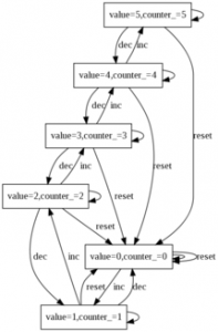
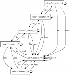
Here we come back on the example of a counter given in the previous section. In this version we have mixed the normal counter and the buggy one. The erroneous behaviour is enabled by a global Boolean constant called BUGGY_COUNTER. Below we give the semantics of the node for both values of the constant.
 1 const BUGGY_COUNTER = false;
 2
 3 const CMAX = 5;
 4 domain COUNTER = [0, CMAX];
 5
 6 node Counter
 7   flow value : COUNTER;
 8   state counter_ : COUNTER;
 9   event inc, dec, reset;
10   trans
11     true |- reset -> counter_ := 0;
12     BUGGY_COUNTER |- inc -> counter_ := 0;
13     counter_ < CMAX |- inc -> counter_ := counter_ + 1;
14     counter_ > 0 |- dec -> counter_ := counter_ - 1;
15   assert
16     counter_ = value
17 edon
| BUGGY_COUNTER=false | BUGGY_COUNTER=true | |
 |
 |
Example 3
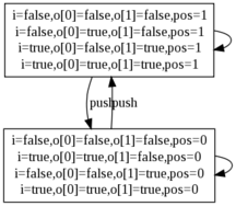
The following example is a switch that directs an “input” stream to one way or another. An event called push is used to describe the action of a user. The event changes the current position pos of the switch. The assertion describes where the stream is connected. As previously the semantics of the node is given after the AltaRica code below; this time we gather all configurations that correspond to a position of the switch (i.e. pos = 0 or 1). The semantics of arrows between bundles of configurations mean that there exists a transition between each configuration of both bundles. In particular the reader should notice that transitions labelled by ε (i.e. without label on the picture) make a loop, that means that flows of the node can change without any modification of the internal state (i.e. position) of the switch.
 1 node Switch
 2   flow
 3     i : bool;
 4     o : bool[2];
 5   state
 6     pos : [0, 1];
 7   event
 8     push;
 9   trans
10     true |- push -> pos := (pos + 1) mod 2;
11   assert
12     i = (if pos = 0 then o[0] else o[1]);
13 edon
