The AltaRica language permits to describe systems in a bottom-up manner. Elementary components can be composed to form complex equipments with their own interfaces and behaviours. The hierarchical nodes are described like the other ones (see the previous section) but they are allowed to declare subnodes and to control interactions of their interfaces i.e. interactions between their flows and between their events.
Subnodes
A compound node declares its components using the sub keyword. The syntax is similar to the one used for the declaration of variables: a comma-separated list of subnodes identifiers followed by a semi-colon and a type of nodes. Subnodes can be hierachical ones. Example:
 1 node A ... edon
 2
 3 node B
 4   sub
 5     a : A;
 6 edon
 7
 8 node C
 9   sub
10     a0, a1, a2 : A;
11     b, bb : B;
12 edon
The array notation can be used to declare vectors of the same node type; for instance the node C above could be rewritten as follows:
1 node C
2   sub
3     a : A[3];
4     b : B[2];
5 edon
The size of the array must be a constant expression.
Initialization
A compound node can change the initial assignments of its sub-nodes; at any depth of the hierarchy. The dot notation (.) is used to specify state variables of sub-nodes. Example:
 1 domain D = [0,3];
 2
 3 node A
 4   state x : D;
 5   init x := 0;
 6 edon
 7
 8 node B
 9   sub a : A[2];
10   state x : D;
11   init x := 0, a[0].x := 1;
12 edon
13
14 node C
15   sub b : B
16   init b.x := 1, b.a[0].x := 3, b.a[1].x := 2;
17 edon
Connecting flows
Flows of nodes can be connected. This concept is formalized by assertions on flow variables of sub-nodes; by default only flows of direct sub-nodes are available. As others invariants, connecting constraints must be satisfied for all configurations of the node and its sub-nodes. The following example describe a compound node called Main that embeds 3 sub-nodes: a generator and two transfer functions. The system is represented graphically below. Assertions specified in the node Main enforces the “connection” of flows between nodes.

 1 node Generator
 2   flow f : Data;
 3   ...
 4 edon
 5
 6 node TrFunction
 7   flow f : Data[2];
 8   ...
 9 edon
10
11 node Main
12   sub g : Generator
13       tf : TrFunction[2];
14   assert
15     g.f = tf[0].f[0];
16     tf[0].f[1] = tf[1].f[0];
17 edon
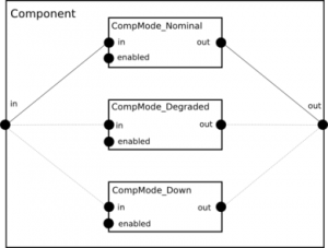
As written above, compound nodes can constrain flows of sub-nodes using any kind of AltaRica expression. Thus, connections are not restricted to simple equalities and even state variables of the compound node. As instance, consider a node Component having three running modes: nominal, degraded and down. Each mode can be described using a sub-component that has the same interface than the compound node.
 1 domain SomeDomain = ...;
 2
 3 node CompMode_Nominal
 4 flow enabled : bool;
 5      in, out : SomeDomain;
 6 assert enabled => (in = out);
 7 edon
 8
 9 node CompMode_Degraded
10 flow enabled : bool;
11      in, out : SomeDomain;
12 ...
13 edon
14
15 node CompMode_Down
16 flow enabled : bool;
17      in, out : SomeDomain;
18 ...
19 edon
Then Component enables each mode according to its own state variable mode. Finally interfaces of modes and Component are connected according to the value of the mode variable:

 1 node Component
 2   flow  in, out : SomeDomain;
 3   event failure;
 4   state mode : { nominal, degraded, down };
 5   init  mode := nominal;
 6   sub
 7     nominalMode : CompMode_Nominal;
 8     degradedMode : CompMode_Degraded;
 9     downMode : CompMode_Down;
10   trans
11     mode = nominal |- failure -> mode := degraded;
12     mode = degraded |- failure -> mode := down;
13   assert
14     nominalMode.enabled = (mode = nominal);
15     degradedMode.enabled = (mode = degraded);
16     downMode.enabled = (mode = down);
17     case {
18       mode = nominal  :
19         in = nominalMode.in and out = nominalMode.out,
20       mode = degraded  :
21         in = degradedMode.in and out = degradedMode.out,
22       else
23         in = downMode.in and out = downMode.out
24     };
25 edon
Synchronization of events
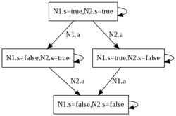
The AltaRica semantics assumes the strict interleaving of events of nodes. For instance if
we consider two nodes N1 and N2, that are able to do an action a then the semantics of the system composed of N1 and N2 is depicted below. The interleaving is strict i.e N1.a and N2.a never occur simultaneously. One should note the presence of ε-transitions that model the fact that none of the nodes do an action.

 1 node N
 2   event a;
 3   state s : bool;
 4   init s := true;
 5   trans s |- a -> s := not s;
 6 edon
 7
 8 node Main
 9   sub
10     N1, N2 : N;
11 edon
It is possible to change the default semantics using synchronization vectors “à la Arnold-Nivat”. Elements of these vectors are events and its semantics enforces all its components to occur at the same time. Subnodes that are not listed in a vector are assumed to be synchronized using the event ε. Several vectors can be specified and an event can occur in several vectors. If a vector is specified then the default semantics for listed events is replaced by the semantics of the vector.
Synchronization vectors are introduced using the sync keyword. Vectors are separated by semi-colons; each one starts with < and end with >. Between these delimiters events of the compound node or events of sub-nodes are given separated by commas.
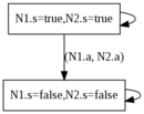
If we come back on the previous example, we can enforce the synchronism of N1.a and N2.a specifying the vector < N1.a, N2.a >. The semantics of the synchronized node Main is given below:

1 node Main
2   sub
3     N1, N2 : N;
4   sync
5     <N1.a, N2.a>;
6 edon
The reader should note the non-causality between events involved in a synchronization. The intuitive semantics of < N1.a, N2.a > is that N1.a must occur when N2.a does but, conversely, N2.a must be present when N1.a occurs. If one of the synchronized event is impossible then the whole synchronization can not occur.